

Tube Leak Detection in Power Plants
In today’s power production environment, thermal cycling is more common which stresses process equipment causing higher tube leak rates. The forced outage rate in 2019 for power plants was 6.97%. Forced outages for combined cycle plants typically cost a plant $110,000 in fines, repairs and lost income. Other causes of tube leaks include acidic / dew point corrosion from process gas and flow accelerated corrosion (FAC). We will review the diagnostic techniques to determine tube leaks in combined cycle power plants.
The Most Common Signs and Forms of Tube leakage
Power plants ideally want to identify a tube leak as soon as possible before it grows and causes a forced outage. Higher water make up usage, audible indicators (hissing) and humidity sensors all indicate there is a tube leak.
Tube Leak Detection Methods
The main three systems for detecting tube leaks are water balances, acoustic sensors and humidity measurements.
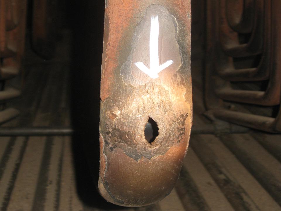
Figure 1: Tube Leak
Water Balance
The most common detection for tube leaks is a water balance on the system. Extra water makeup is a good indicator of a tube leak but sensitivity to small leaks is not easy with this method. This method also doesn’t locate where the tube leak is located within the boiler.
Acoustic Sensing
The second most common detection is using acoustic sensors located throughout a boiler train. The sensors feedback to a computer system which analyzes the signals to determine if a tube leak is happening. These systems are becoming more prevalent due to their ability to locate the location of a tube leak. Acoustic Sensing Systems are also relatively good at picking up early leaks. The downside of the systems is the cost and the added maintenance anytime you add sensors to an industrial environment.
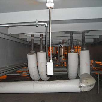
Figure 2: Acoustic Monitoring In Industrial Application
Humidity Monitoring
Installing a humidity sensor after the boiler will also be able to pick up a tube leak because the leak is in the form of steam. The added moisture content to the process gas is picked up by the sensor alerting the plant of a leak. Humidity sensors have to be able to work in harsh environments and also have a very good detection limit. Humidity measurements also have to use all process data including load, ambient conditions, duct burner operation and power augmentation to establish base humidity levels when there are no leaks present.
The benefits of the humidity measurements are low detection limits to pick up small leaks, low cost and they pay for themselves within a year by optimizing feedwater temperature control.
Humidity sensors prevent gas side corrosion by keeping the feedwater temperature above the dew point (acid or water depending on fuel used) of the process gas hence eliminating one cause of tube leaks while optimizing energy usage. The downside of humidity sensors is that they will not pinpoint exactly where the leak is in the boiler train by themselves.
Acoustic and Humidity Sensor Systems
The best technique for identifying tube leaks would be to have a combination of an acoustic system with a humidity sensor. The humidity sensor will have the same if not better detection limit for tube leaks of an acoustic system. The two different values are compared and confirm if a leak is happening. The acoustic system pinpoints the location as well and the humidity sensor pays for itself separately in feedwater optimization.
Humidity 2 Optimizations Line of Sensors for Power Plant Applications
Humidity 2 Optimization provides a reliable absolute humidity measurement for detecting tube leaks in combined cycle power plants. The sensors are installed after the Heat Recovery Steam Generation (HRSG) system, typically at the economizer outlet or at the stack.
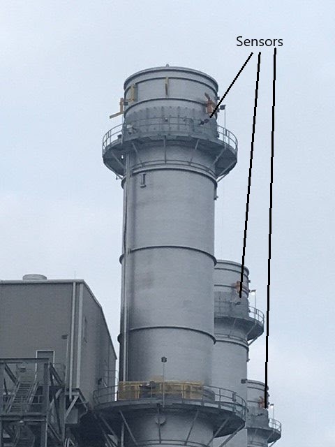
Figure 3: Sensor Stack Locations
The sensor at the stack location will pick up all humidity changes in the process. The variables include load change, ambient humidity changes, power augmentation systems, duct burners and tube leaks. The first four of the variables are repeatable, which allows the sensor to pick up the tube leaks.
The sensitivity of the sensor is 0.1 g/m3 H2O. A typical tube leak detection limit is described below:
Tube Leak Detection – HRSG Outlet Calculation
Our detection limit is 0.1 g/m3 at 0C
Volumetric flow rate: 1,300,000 m3/hr
Detection limit = leak / volumetric flow rate
Leak = .1*1,300,000
Leak = 130,000 g/hr
Leak = 4.78 lbs/min or 0.57 gallons per minute
Other advantages of the sensor at combined cycle plants include feedwater temperature control, energy balance calculations and identification of upset conditions of power augmentation systems and duct burners.